1.1 Simulations?
The Turtlebot3 ROS package will be used for the simulation purpose in some of the planning techniques like potential functions, navigation potential functions, etc. It is the most popular open-source robot for education and research. It has three models: burger, waffle and waffle-pi. Here is the ROS package link.
1.2 Burger Model:
These are the features we should care about.
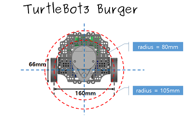
1. It is a differential drive robot with dimensions $138mm × 178mm × 192mm$
2. It has a maximum linear velocity of $0.22 m s^{-1}$ and an angular velocity of $2.84 rad s^{-1}$.
3. It has a $360^{\circ}$ LIDAR, 9-Axis Inertial Measurement Unit, and precise encoders.
More info

Figure 1. Top View of Burger Model
1.3 Configuration:
The robot can move only in the 2D plane, $(x,y,\theta)$ is enough to represent its configuration $q$. Therefore, the dimensions of the configuration space $Q$ will be $R^{2} \times S^{1}$.
$q = (x,y,\theta) \in Q = R^{2} \times S^{1} \tag{1}$
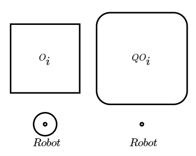
In most of the problems, we will be considering the robot as a circle of radius $r$ for easier implementation. This will eliminate the effect of $\theta$ on the configuration space. An example can be seen below:
Figure 2. Configuration Space Obstacle
1.4 ROS Topics:
* /scan - get laser data of an array of size 360, each index corresponds to each angle
* /odom - get (x,y) coordinates of the robot
* /imu  - get orientation of the robot
* /cmd_vel - publish desired linear and angular velocity of the robot
1.5 Orientation Control:
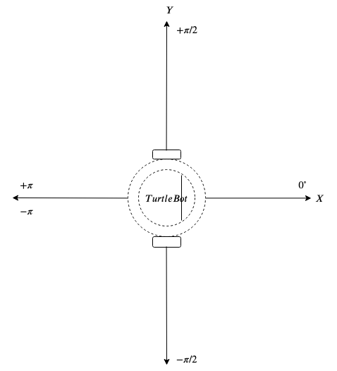
For navigation, we need to generate required angular velocity $\omega$ to acquire desired orientation/direction of motion. A simple PD controller can be used with feedback of orientation from /imu topic. In Figure 3, the conventions of the orientation can be seen. We can see there's a jump from $+\pi$ to $-\pi$ which can create a problem when the current orientation is positive and the desired orientation is negative. Converse of which is also problematic. The robot will take a longer path to attain the desired orientation because this is how the rotation works! Positive$\rightarrow$Zero$\rightarrow$Negative or Negative$\rightarrow$Zero$\rightarrow$Positive but never Postive$\rightarrow$Negative or Negative$\rightarrow$Positive. This needs to be handled.

Figure 3. Conventions
